When using this instrument, please do not look directly at the optical interface or the end of the opticalfiber with your eyes, avoid eye damage! Any change or modification not explicitly permitted in this manualwill deprive you of the right to operate the equipment. To reduce the risk of fire or electric shock, do notexpose the equipment to thunderstorm or humid environment. In order to prevent electric shock, do notopen the shell, it must be repaired by the qualified personnel designated by the manufacturer.
Attention
Battery: The battery in the machine is a special lithium-ion polymer battery. The charging voltage is 5V,and the charging temperature ranges from 0℃~50℃. When the ambient temperature is too high, thecharging will automatically terminate. The instrument battery should be charged every one month to avoidbattery failure due to self-discharge after long time storage. The temperature range of the battery duringlong-term storage is -20℃~45℃.Please use the special AC adapter attached to this instrument and use the external power supply strictlyaccording to the specifications, otherwise the equipment may be damaged.
Fiber End Face Cleaning: Before testing, clean the end face of the tested optical fiber joint with alcoholcotton.
LCD screen: The display of this series of instruments is 3.5 inch color LCD. In order to maintain goodviewing effect, please keep the LCD screen clean and clean. When cleaning, the LCD screen can be cleanedby wiping with soft fabric.
Guarantee description:
The whole machine is guaranteed for 18 months. The battery, charging adapter and optical interfaceconsumables are guaranteed for 6 months. The warranty date shall be postponed one month from the date of manufacture.
Due to the need of design improvement, the contents are subject to change without notice.
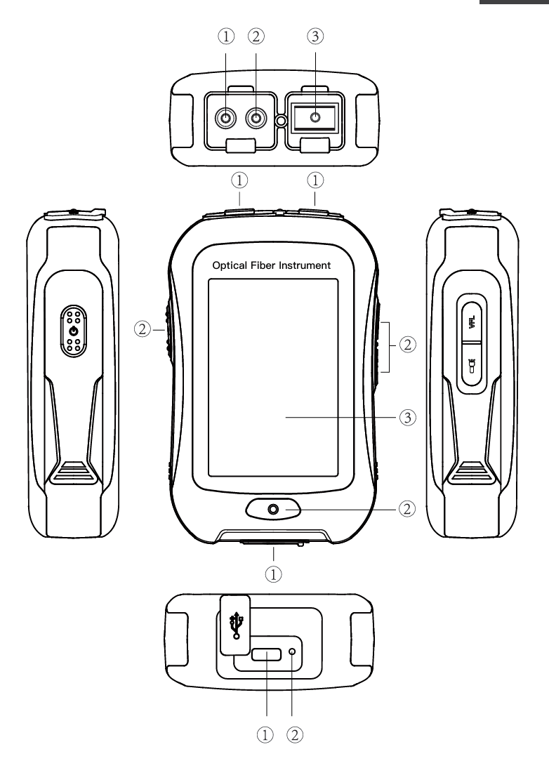
Brief Top view Main view Back view
① OPM port ① Dust Cover ① Type C USB
② VFL port ② Function Keys ② LED Charging indicator
③ OTDR/LS port ③ 3.5 inch Color LCD
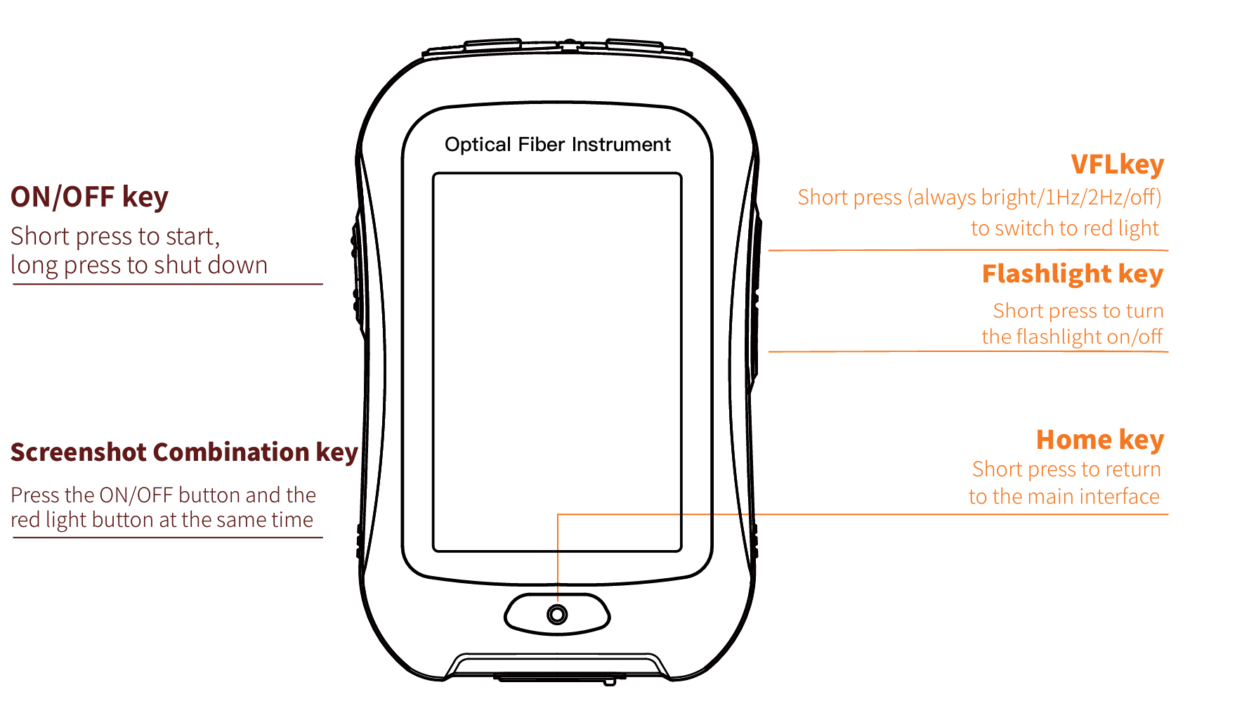
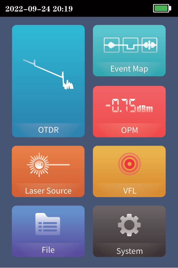
Functional Keys Main Interface Enter the main menu after power on, there are 7 function modules. Press the function icon to enter the corresponding function interface Date &Time Flashlight Battery LS USB VFL
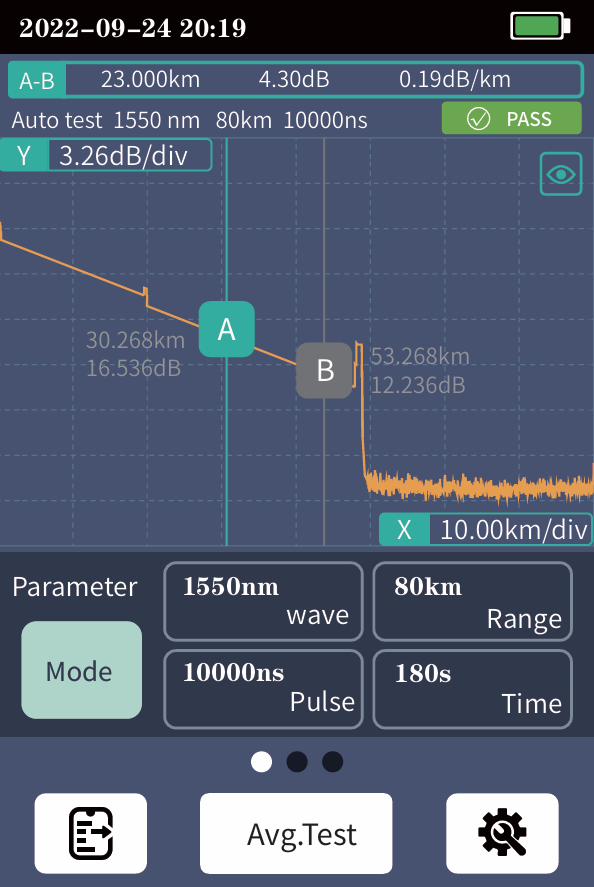
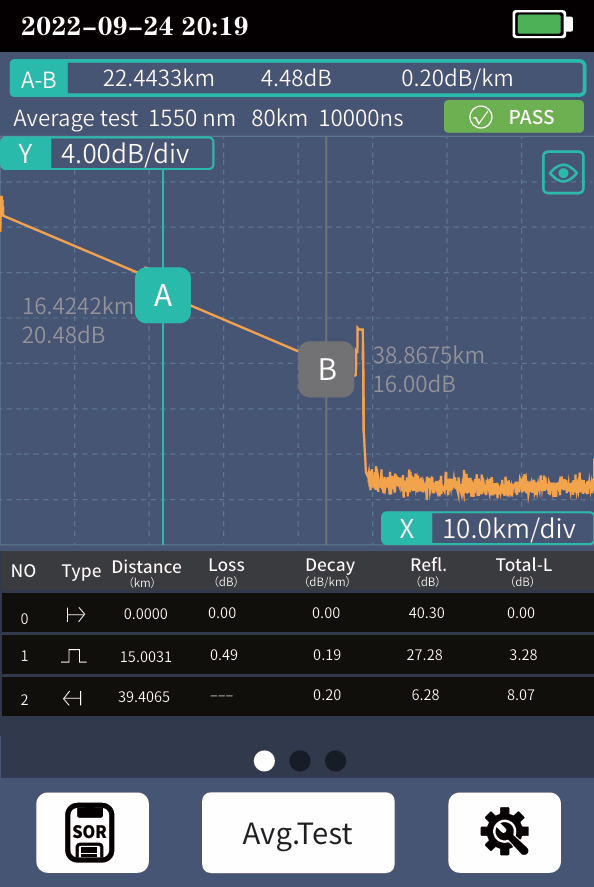
OTDR-Curve Setting parametes :Select the test wavelength, range, pulse width and time Mode switching:Real time test, average test and auto test mode switching Wavelength:Select the test wavelength of OTDR Test range:Usually required to be set about twice the length of the measured optical fiber Test pulse width:5ns~10000ns optional, different measuring ranges, different pulse widths are available Curve Operation Curve Zoom, drag:Touch screen gesture operation Restore initial curve:Double click the screen Move Cursor:Drag A or B
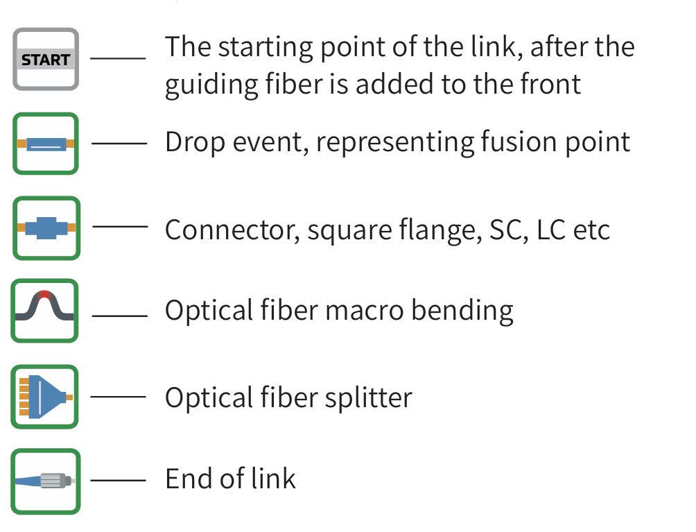
OTDR List List: the tested results are displayed in the form of a list. A-B Total length: the total length of the link under test. A-B Total loss: the total loss of the link under test. A-B Slope: the loss per kilometer of the link under test. In the event list: NO.: the order of the current event. Type: the type of the current event. Distance: the location of the current event. Loss: the loss of the current event. Decay: the loss from the starting point to the current event. Reflection: the return loss of the current event. Total loss: the loss from the starting point to the current event. There are five types of events:
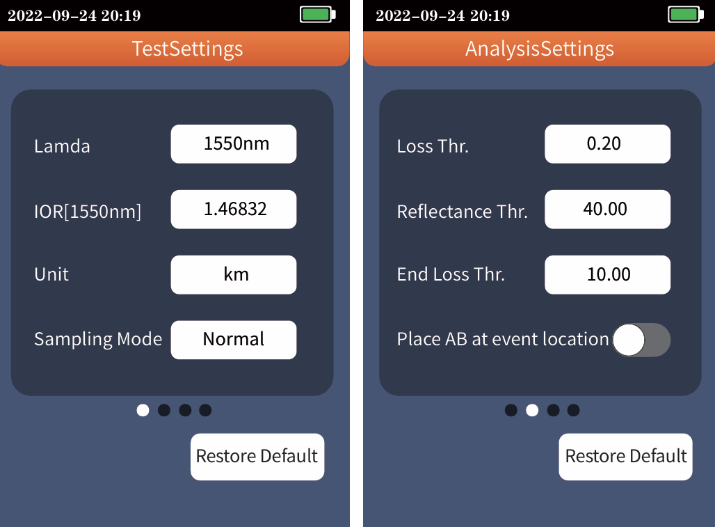
OTDR Setting Setting parametes wavelength, select the test unit and sampling mode Test units include km, mi and kft There are three measurement modes: fast, conventional and high-precision Analysis parameter/threshold setting Set the reflection threshold, non reflection threshold and end threshold required for event analysis Event loss threshold: set the loss threshold of connection point, fusion point or macro bend in the link that can be tested, between 0.2~30dB, and the default value is 0.2dB. Events larger than the set threshold will be listed in the event table, or those will be ignored. Reflection threshold: set the return loss threshold of the link reflection events that can be tested, ranging from 10dB to 60dB, and 40dB by default. End threshold: set end loss at the end of the link that can be tested, ranging from 1~30dB, 10dB by default.Reflection threshold: set the return loss threshold of the link reflection events that can be tested, ranging from 10dB to 60dB, and 40dB by default. End threshold: set end loss at the end of the link that can be tested, ranging from 1~30dB, 10dB by default.
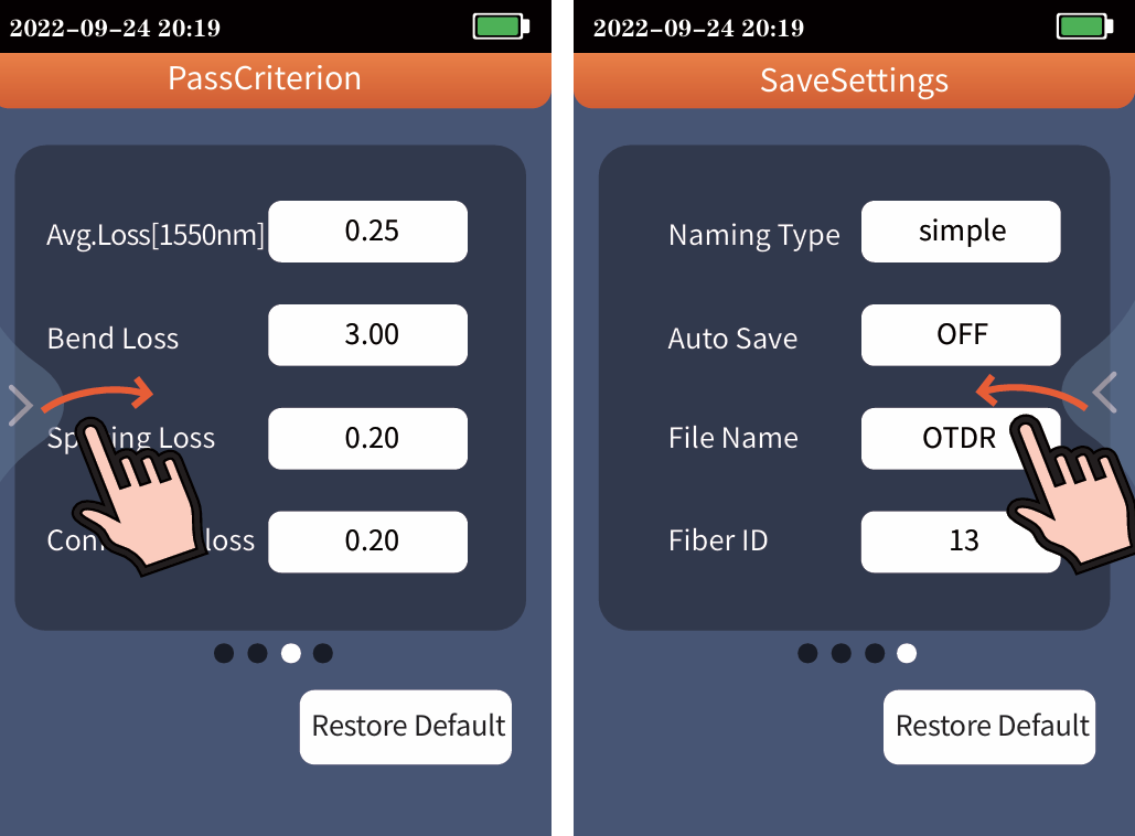
OTDR Setting Acceptability criterion Set the judgment value for the average loss of connection/fusion/bend ing/link. If it is less than the value, it is judged as "PASS", otherwise it is "FAIL" Average loss: the loss value per kilome ter of the link under test Bending loss: non reflective events caused by fiber bending, need to be tested at two wavelengths at once Welding loss: non reflective event, refers to fusion Connection loss: reflection event, refers to flange, SC, LC and other joints Set return: the gesture slides from the right or left
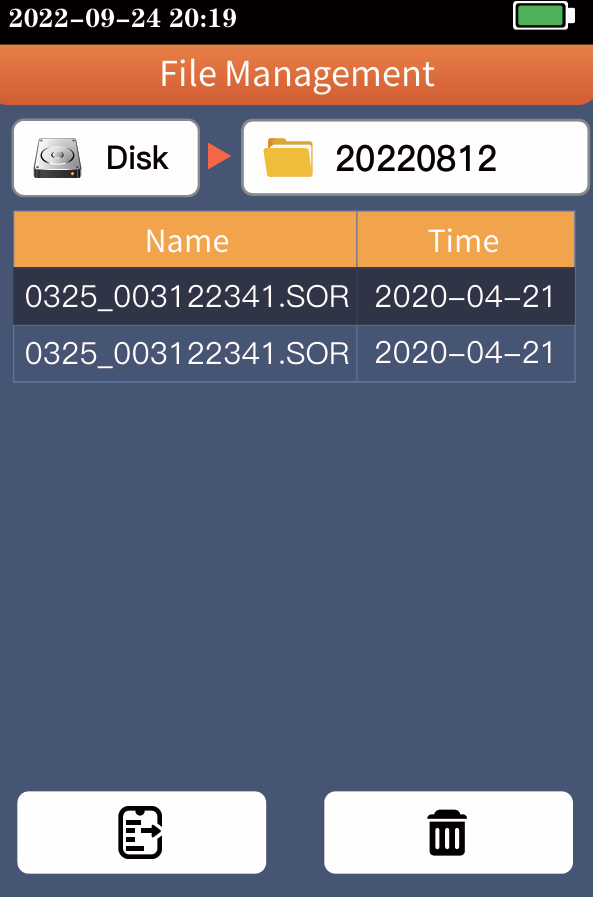
File Operation Save Settings Simple: File name is "file name prefix (default" otdr ") - serial number", and the serial number increases in sequence. Detailed: File name is "file name prefix - range - pulse width - serial number", and the serial number increases in sequence Auto Save:Automatic saving of test curve after opening File name:File name prefix Fiber ID:the serial number of the current optical fiber File operation All test curves are saved in the internal disk of the instrument. Press [File] to enter the file operation interface, where you can open and delete files.
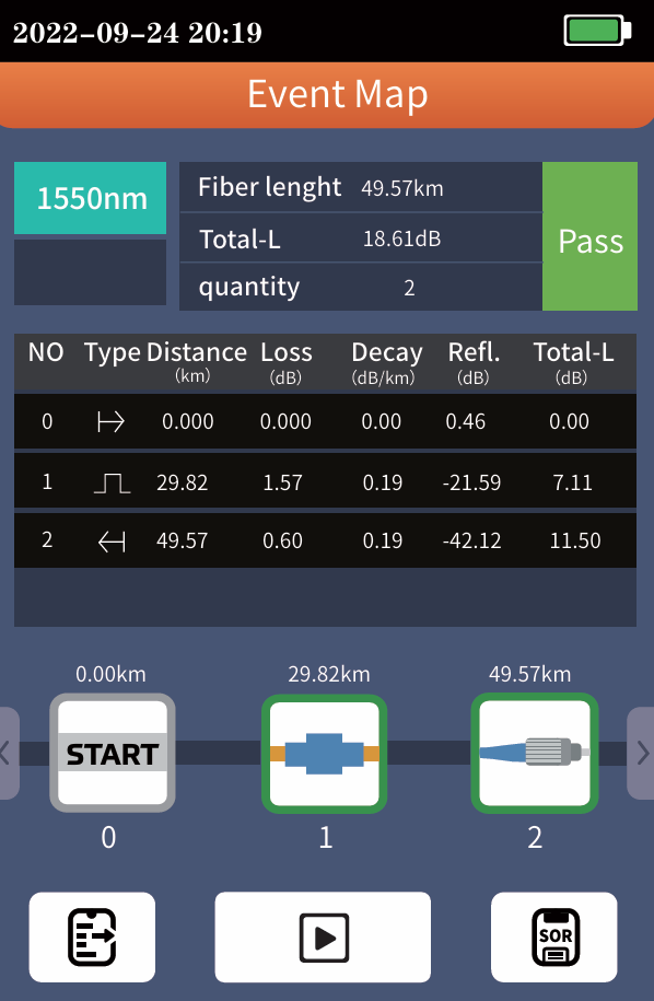
Event Map The function is fully one key automatic test, and the information such as the length of the optical fiber link to be measured, the type of the joint and the position of the breakpoint are displayed graphically, and the results are clear and easy to understand
OPM It is used for signal power test and insertion loss test of various equipment and photoelectric components. It can identify and measure the power of 270/ 330/1k/2kHz frequency laser. :Switching the operating wavelength of the power meter, wavelength switching 850, 980, 1300, 1310, 1490, 1550, 1625, 1650 nm :Set the current power as the reference power :Enter the user calibration mode, coordinate with the standard light source to calibrate the power The conversion relations of absolute power, relative power and linear power are as follows: PAbs.Pow=10lgPLin.Pow/1mW PRel.Pow=PAbs.Pow-PRef.Pow
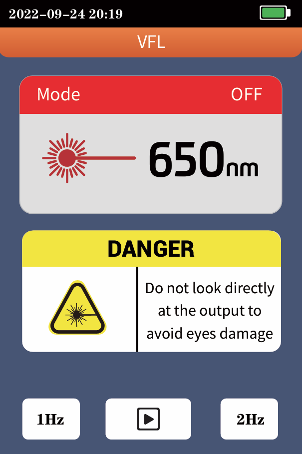
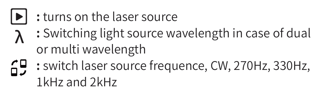
VFL Inject the visible red light (650nm) into the optical fiber, and observe the light leakage position on the measured fiber, which can easily and accurately determine the position of the optical fiber fault point. It is applicable to the detection of the near end failure point of bare optical fiber, optical fiber jumper and other optical fiber and optical cable that can pool red light and the high loss section caused by micro bending Turn on the red light source and work continuously 1Hz:Red light source flashes once a second 2Hz:Red light source flashes twice in one second Turn off the red light source Warning Avoid looking directly at the laser output port, because the laser will cause damage to the human retina!
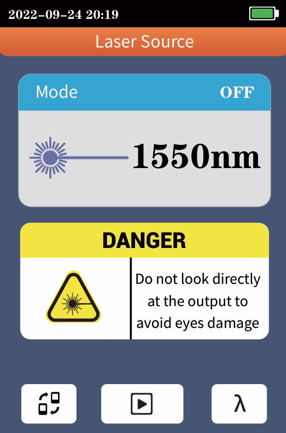
Laser Source The output laser with the same wavelength as OTDR function, which can be used to test the parameters of telecommunication, CATV and LAN optical cables, test the insertion loss, isolation and return loss of optical passive components, and test the wavelength respon sivity of detector. There are five working modes : CW, 270Hz, 330Hz, 1kHz and 2kHz. Warning Avoid looking directly at the laser output port, because the laser will cause damage to the human retina!
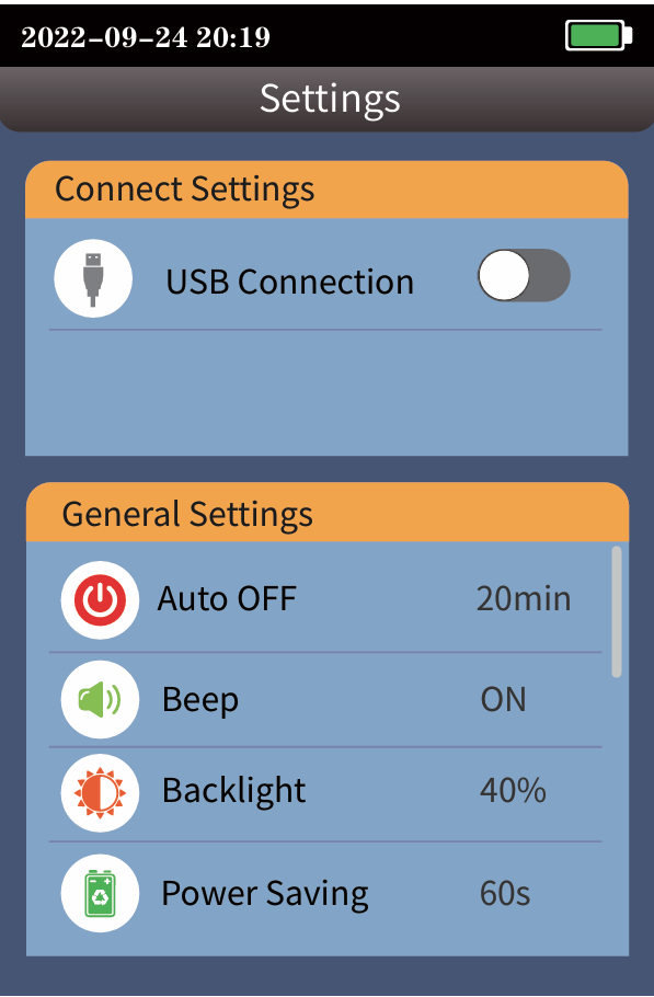
SET AUTOMATIC SHUTDOWN, BACKLIGHT BRIGHTNESS, TIME,LANGUAGE AND OTHER INFORMATION USB connection:Connect the computer through Type-C, and make the device into a virtual USB flash disk, which can export files inside the device Automatic shutdown:5/10/20/45/90 minutes voice:Turn touch tone on or offBacklight brightness:0%~100% brightnessPower saving settings:20/30/60/120s automatic screen outtime:Set instrument timedate:Set instrument dateLanguage Settings:Set native language typeRestore factory settings:Restore default parameter valuesSD card format:Delete all files on this computerupgrade:Native software updatesVersion information:View local information and alarmrecords
Ricevi offerte esclusive e novità che allieteranno la tua giornata!
Utilizziamo i Cookie per migliorare la tua esperienza online. Continuando la navigazione su questo sito assumiamo che tu acconsenta al nostro utilizzo dei Cookie.


 :Switching the operating wavelength of the power
  :Set the current power as the reference power
 :Enter the user calibration mode, coordinate with
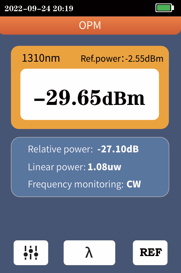
 Turn on the red light source and work continuously
 Turn off the red light source